


FM24W256-GTR Infineon | 256Kb I2C F-RAM Memory Technical Guide
Product Technical Guide FM24W256-GTR 256Kb I2C Ferroelectric RAM Technical GuideInfineon Technologies 256-Kbit nonvolatile F-RAM memory featuring a 32K × 8 organization, I2C interface up to 1MHz, inst…
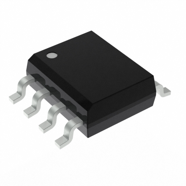
- Part No.:
- FM24W256-GTR
- Manufacturer:
- Infineon Technologies
- Package:
- 8-SOIC (0.154", 3.90mm Width)
- Datasheet:
- FM24W256-GTR.pdf
- Description:
- IC FRAM 256KBIT I2C 1MHZ 8SOIC
- Quantity:
-
Original Supply
Strict supplier screening and quality control support.
-
Datasheet Support
Help engineers quickly verify product specifications.
-
BOM Sourcing
Support multi-part procurement and RFQ matching.
FM24W256-GTR Infineon | 256Kb I2C F-RAM Memory Technical Guide
Infineon Technologies 256-Kbit nonvolatile F-RAM memory featuring a 32K × 8 organization, I2C interface up to 1MHz, instant NoDelay writes, 100 trillion read/write cycles, 2.7V to 5.5V operation, and industrial-temperature SOIC-8 packaging.
Product Introduction
The FM24W256-GTR is a 256-Kbit nonvolatile ferroelectric random access memory (F-RAM) manufactured by Infineon Technologies, formerly supplied under the Cypress Semiconductor product portfolio.
The device provides 262,144 bits of memory organized as 32,768 × 8. It uses an industry-standard I2C serial interface, allowing communication with microcontrollers, embedded processors, and other digital control devices through a two-wire bus.
Unlike conventional EEPROM, which requires an internal programming cycle after writing data, the FM24W256-GTR performs memory writes at bus speed. Its NoDelay write operation eliminates the typical EEPROM write-cycle waiting period and the need for acknowledgment polling.
The F-RAM technology provides exceptionally high write endurance, supporting 100 trillion (10¹⁴) read/write cycles across its specified operating temperature range. This makes the device particularly suitable for applications involving continuous event logging, frequently updated counters, and real-time parameter storage.
Data remains stored when power is removed. The device offers a specified minimum retention of 151 years at 65°C, with retention depending on temperature.
The FM24W256-GTR operates from 2.7V to 5.5V and supports I2C clock frequencies up to 1MHz. It is compatible with standard 100kHz, fast 400kHz, and 1MHz I2C communication modes.
The device is supplied in an 8-pin SOIC package and operates over the industrial ambient temperature range of -40°C to +85°C.
For engineers designing data-intensive embedded systems, the FM24W256-GTR offers a practical alternative to conventional serial EEPROM when write speed, endurance, and nonvolatile data integrity are important.
Key Benefits
Instant Write Operation
NoDelay technology enables writes at I2C bus speed without EEPROM-style internal write-cycle delays.
Exceptional Endurance
Supports 100 trillion read/write cycles for applications that continuously update stored information.
Nonvolatile Data Storage
Retains data without power, with a specified minimum retention of 151 years at 65°C.
EEPROM-Compatible Interface
Uses a standard I2C interface and familiar 8-pin serial-memory pin arrangement to simplify integration.
Features
- 256-Kbit nonvolatile ferroelectric random access memory
- Memory organization of 32K × 8 bits
- 32,768 individually addressable bytes
- Industry-standard two-wire I2C serial interface
- Maximum I2C clock frequency of 1MHz
- Supports 100kHz, 400kHz, and 1MHz I2C operation
- NoDelay instant write technology
- No internal EEPROM-style programming delay
- No write-completion polling required
- 100 trillion (10¹⁴) read/write endurance cycles
- 151-year minimum data retention at 65°C
- 38-year minimum data retention at 75°C
- 10-year minimum data retention at 85°C
- Single supply voltage from 2.7V to 5.5V
- 100µA maximum average supply current at 100kHz I2C operation
- 15µA typical standby current
- 400µA maximum average supply current at 1MHz
- Byte and sequential read operations
- Byte and sequential write operations
- Three hardware device-address selection inputs
- Supports up to eight devices on one I2C bus through address selection
- Hardware write-protect input
- Open-drain SDA interface
- Schmitt-trigger input circuitry for noise immunity
- Industrial operating temperature range from -40°C to +85°C
- 8-pin SOIC surface-mount package
- Tape-and-reel packaging
- Lead-free and RoHS-compliant construction
Design Note: The FM24W256-GTR is designed for applications requiring frequent nonvolatile writes. Although it can serve as a hardware replacement for many I2C EEPROM devices, software timing, address behavior, and write-protection handling should be reviewed before substitution.
Package
The FM24W256-GTR is supplied in an 8-pin SOIC surface-mount package. The package is identified by Infineon as PG-DSO-8, corresponding to the manufacturer's 51-85066 mechanical drawing.
- Package Type: SOIC-8
- Infineon Package: PG-DSO-8
- Package Drawing: 51-85066
- Pin Count: 8
- Mounting Type: Surface Mount
- Nominal Body Width: Approximately 3.9mm
- Nominal Body Length: Approximately 4.9mm
- Lead Pitch: 1.27mm
- Packaging Format: Tape and Reel
- Standard Reel Quantity: 2,500 pieces
- Moisture Sensitivity Level: MSL 3
- Peak Reflow Temperature: 260°C
- Lead Finish: Pure Tin
- RoHS Compliance: Yes
- Lead-Free: Yes
- Halogen-Free: Yes
The compact SOIC-8 footprint allows the device to be integrated into industrial controllers, measurement instruments, communication modules, and embedded systems with limited PCB space.
The G suffix identifies the SOIC package option, while the TR suffix indicates tape-and-reel packaging.
For PCB design, use the official package drawing to verify pad dimensions, lead spacing, assembly clearances, and soldering requirements.
Pinout
The FM24W256-GTR pinout uses the standard eight-pin arrangement found in many serial I2C nonvolatile memory devices.
| Pin | Signal | Function |
|---|---|---|
| 1 | A0 | Hardware device-address selection input, bit 0. |
| 2 | A1 | Hardware device-address selection input, bit 1. |
| 3 | A2 | Hardware device-address selection input, bit 2. |
| 4 | VSS | Ground reference. |
| 5 | SDA | Bidirectional I2C serial data input/output. |
| 6 | SCL | I2C serial clock input. |
| 7 | WP | Hardware write-protect input. |
| 8 | VDD | Positive supply voltage input, 2.7V to 5.5V. |
Address Selection: The A0, A1, and A2 pins define the lower three bits of the seven-bit I2C slave address. The device-address range is 0x50 to 0x57, depending on the external address-pin configuration.
Write Protection: Connecting WP to VDD protects the entire memory array against write operations. Connecting WP to VSS enables writing. The WP input includes an internal pull-down.
I2C Connections: SDA is an open-drain signal and requires an external pull-up resistor. The pull-up resistance should be selected according to supply voltage, bus capacitance, rise-time requirements, and operating frequency.
Important: Verify the top-view orientation and pin-one marking using the official Infineon package drawing before finalizing the PCB footprint.
Specifications
| Parameter | Value |
|---|---|
| Part Number | FM24W256-GTR |
| Manufacturer | Infineon Technologies |
| Legacy Brand | Cypress Semiconductor |
| Memory Technology | Ferroelectric RAM (F-RAM) |
| Memory Type | Nonvolatile |
| Memory Capacity | 256Kbit |
| Memory Organization | 32K × 8 |
| Addressable Bytes | 32,768 |
| Interface | I2C |
| Maximum Clock Frequency | 1MHz |
| Supported I2C Frequencies | 100kHz, 400kHz, 1MHz |
| Supply Voltage Range | 2.7V to 5.5V |
| Typical Supply Voltage | 3.3V |
| Maximum Active Current at 100kHz | 100µA |
| Maximum Active Current at 400kHz | 200µA |
| Maximum Active Current at 1MHz | 400µA |
| Typical Standby Current | 15µA |
| Maximum Standby Current | 30µA |
| Write Technology | NoDelay Instant Writes |
| Read/Write Endurance | 10¹⁴ Cycles Minimum |
| Data Retention at 65°C | 151 Years Minimum |
| Data Retention at 75°C | 38 Years Minimum |
| Data Retention at 85°C | 10 Years Minimum |
| Hardware Address Pins | A0, A1, A2 |
| Maximum Devices per I2C Address Group | 8 |
| I2C Seven-Bit Address Range | 0x50 to 0x57 |
| Hardware Write Protection | Yes, Entire Memory Array |
| Operating Temperature Range | -40°C to +85°C |
| Temperature Classification | Industrial |
| Package Type | SOIC-8 |
| Package Code | PG-DSO-8 |
| Pin Count | 8 |
| Mounting Type | Surface Mount |
| Packaging | Tape and Reel |
| Standard Reel Quantity | 2,500 |
| Moisture Sensitivity Level | MSL 3 |
| RoHS Compliance | Yes |
| Product Status | Active and Preferred |
Memory Endurance: The 10¹⁴-cycle endurance specification is significantly higher than that of typical EEPROM devices. This makes the FM24W256-GTR suitable for frequently updated data, including operating counters and event records.
Write Performance: The device completes memory writes at I2C bus speed. It does not require the internal programming delay associated with EEPROM, so the host can begin a subsequent transaction without waiting for a write cycle.
Retention Performance: Data retention depends on operating temperature. The specified minimum retention is 151 years at 65°C, 38 years at 75°C, and 10 years at 85°C. These figures should not be treated as a uniform lifetime guarantee under every operating condition.
Power Consumption: Maximum average supply current is 100µA at 100kHz, 200µA at 400kHz, and 400µA at 1MHz under the datasheet's specified test conditions.
System Design: Use a stable supply, appropriate bypass capacitance, suitable I2C pull-up resistors, and proper power-on initialization to support reliable memory operation.
Equivalent
When selecting an FM24W256-GTR equivalent or replacement, engineers should compare memory capacity, I2C protocol compatibility, supply voltage, device addressing, package footprint, write-protect behavior, endurance, and nonvolatile data retention.
FM24W256-G: The same base memory device in SOIC-8 packaging without the tape-and-reel suffix. It is the closest ordering variant, subject to current manufacturer availability and packaging requirements.
FM24W256-EGTR: A related 256-Kbit F-RAM ordering option using an EIAJ SOIC package. Its physical dimensions and PCB footprint differ from the G package. It is not a guaranteed footprint-compatible substitute.
FM24CL256: A related 256-Kbit I2C F-RAM device from the same historical product portfolio. Supply-voltage range, operating conditions, and package details must be checked before replacement.
24LC256 EEPROM: A widely used 256-Kbit I2C EEPROM offering similar logical capacity and a familiar serial interface. It may be considered for systems with infrequent writes, but it has different write timing, endurance, and memory technology.
AT24C256 EEPROM: Another 256-Kbit I2C nonvolatile memory option. It requires software and performance evaluation because conventional EEPROM write cycles are fundamentally different from F-RAM operations.
Replacement Recommendation: For an existing FM24W256-GTR design, prioritize the original part or a manufacturer-approved equivalent. EEPROM alternatives should not be treated as functionally identical when the application depends on high-frequency writing or immediate write completion.
Qualification Checklist: Confirm the exact pinout, supply voltage, address range, memory organization, write protection, endurance, data retention, timing, temperature rating, and PCB footprint before approving a substitute.
Manufacturer
Infineon Technologies AG is a global semiconductor manufacturer providing power semiconductors, microcontrollers, security products, sensors, and memory technologies for automotive, industrial, and embedded electronic systems.
The FM24W256-GTR originated from the Ramtron and Cypress F-RAM product portfolio and is now marketed under Infineon Technologies.
F-RAM combines nonvolatile data retention with fast memory access and high write endurance, making it useful for applications that cannot tolerate the write delays or endurance limitations of conventional EEPROM.
Infineon identifies the FM24W256-GTR as an active and preferred product.
Official Product Page: FM24W256-GTR – Infineon Technologies
Official Datasheet: FM24W256 256-Kbit Serial I2C F-RAM Datasheet
Manufacturer Website: www.infineon.com
For procurement, verify the original manufacturer, complete ordering number, product marking, lot traceability, packaging, and environmental compliance information.
Applications
Industrial Automation
Nonvolatile storage of controller settings, operating counters, machine states, and frequently updated production data.
High-Frequency Data Logging
Fast storage of sensor readings, event records, and operating history without conventional EEPROM write-cycle delays.
Smart Metering
Persistent storage of consumption counters, calibration parameters, and operational records in metering equipment.
Embedded Control Systems
Retention of configuration parameters, runtime variables, and system status across power interruptions.
Measurement Instruments
Reliable storage of instrument settings, calibration values, and frequently updated test records.
Power Management Equipment
Nonvolatile logging of operating conditions, fault events, and configuration settings in compatible power electronics.
Typical Application Circuit: A microcontroller communicates with the FM24W256-GTR through the SDA and SCL pins. Both signals connect to the shared I2C bus, with pull-up resistors to the appropriate supply voltage.
The A0, A1, and A2 pins are connected to logic high or low to establish the desired I2C address. Up to eight FM24W256 devices can share the same bus when each has a unique address configuration.
The WP pin can be connected to ground for normal write operation or driven high when hardware write protection is required.
A suitable ceramic bypass capacitor should be placed near VDD and VSS. The PCB layout should minimize noise on the supply and I2C lines, especially in industrial environments.
Power-Loss Consideration: The nonvolatile memory retains completed writes after power removal. However, the host system must still ensure that valid data and complete transactions are transmitted before supply voltage falls outside the specified operating range.
Engineering Recommendation: For applications with frequently updated counters or event logs, the FM24W256-GTR can reduce software complexity by eliminating EEPROM-style write delays and write-completion polling.
Disclaimer
This technical guide is provided for general product identification, engineering reference, and procurement support. All specifications, pin assignments, memory capacity, write endurance, data retention, interface timing, electrical characteristics, package dimensions, environmental compliance information, and lifecycle status should be verified against the latest Infineon Technologies documentation before design or purchase. Retention and endurance specifications apply under defined operating conditions. Suggested alternatives are not guaranteed direct replacements. Actual system performance depends on power supply quality, PCB layout, I2C bus configuration, operating temperature, and firmware implementation. Product prices and availability may change without notice.

