


Electronic Component Technical Guide
MSP430F413IPMR – Ultra-Low-Power 16-Bit Microcontroller
The MSP430F413IPMR is an ultra-low-power 16-bit microcontroller from Texas Instruments, designed for battery-powered measurement equipment, handheld instruments and embedded control applications. Featuring an 8MHz MSP430 CPU, 8KB Flash memory, 256B RAM, an integrated 96-segment LCD driver and multiple power-saving modes, it provides an efficient solution for low-power embedded system designs.
01. Product Introduction
The MSP430F413IPMR is a 16-bit mixed-signal microcontroller developed by Texas Instruments. It belongs to the MSP430x41x family and is designed for applications requiring low power consumption, reliable embedded processing and integrated LCD control.
The device features an 8MHz MSP430 RISC CPU, 8KB Flash memory and 256 bytes of RAM. Its architecture is optimized for efficient instruction execution and low-power operation, making it suitable for battery-operated electronic products.
One of its main advantages is the integrated LCD driver, which supports up to 96 LCD segments. This capability allows the microcontroller to control display functions without requiring a separate external LCD controller in compatible designs.
The MSP430F413IPMR also integrates a 16-bit Timer_A, Comparator_A, watchdog timer, basic timer and multiple GPIO interfaces. These peripherals support measurement, timing, monitoring and control functions in compact embedded systems.
The device operates with a supply voltage ranging from 1.8V to 3.6V and provides five power-saving modes. Its digitally controlled oscillator (DCO) supports wake-up from standby mode in less than 6µs under specified conditions.
The IPMR ordering code identifies the 64-pin LQFP package supplied in tape-and-reel packaging, making it suitable for automated surface-mount manufacturing.
Product Overview:
- Part Number: MSP430F413IPMR
- Manufacturer: Texas Instruments
- Product Family: MSP430x4xx
- Core Processor: MSP430 16-Bit RISC
- Maximum CPU Frequency: 8MHz
- Flash Memory: 8KB + 256 Bytes
- RAM: 256 Bytes
- LCD Driver: Up to 96 Segments
- Timer: 16-Bit Timer_A3
- Comparator: Comparator_A
- Supply Voltage: 1.8V to 3.6V
- GPIO: 48 I/O Pins
- Power-Saving Modes: 5
- Package: LQFP-64
- Package Drawing: PM
- Operating Temperature: -40°C to +85°C
02. Key Benefits
Ultra-Low-Power Operation
The MSP430F413IPMR is designed for energy-efficient embedded applications. Its five low-power modes help reduce current consumption when the CPU and peripherals are not actively processing data.
Efficient 16-Bit Processing
The integrated 16-bit RISC CPU provides efficient instruction execution and supports measurement and control applications that do not require high-performance 32-bit processing.
Integrated 96-Segment LCD Driver
The built-in LCD driver supports up to 96 segments, helping simplify the design of digital meters, portable instruments and display-based electronic products.
Fast Wake-Up Performance
The digitally controlled oscillator supports wake-up from standby mode in less than 6µs under specified conditions, helping reduce unnecessary active time.
Integrated Analog Comparator
Comparator_A provides analog signal comparison capabilities for threshold detection, monitoring and measurement applications.
Flexible Timing Functions
The integrated 16-bit Timer_A3 supports capture and compare operations, making it useful for timing, pulse measurement and control functions.
Low-Voltage Operation
The 1.8V to 3.6V supply range supports low-voltage embedded designs and battery-powered equipment.
03. Features
- 16-bit MSP430 RISC CPU architecture.
- Maximum operating frequency of 8MHz.
- 16-bit registers and constant generators.
- 125ns instruction cycle time.
- 8KB Flash memory plus 256 bytes.
- 256 bytes of RAM.
- Integrated LCD driver supporting up to 96 segments.
- 16-bit Timer_A3 with three capture/compare registers.
- Integrated Comparator_A.
- 15/16-bit watchdog timer.
- Basic Timer1.
- Frequency-Locked Loop (FLL+).
- Digitally Controlled Oscillator (DCO).
- Five low-power operating modes.
- Active current of 200µA at 1MHz and 2.2V under specified conditions.
- Standby current of 0.7µA under specified conditions.
- Off-mode current of 0.1µA with RAM retention under specified conditions.
- Wake-up from standby in less than 6µs.
- 48 GPIO connections.
- Brownout detection.
- Power-on reset functionality.
- JTAG debugging interface.
- Serial onboard programming.
- Programmable code protection through a security fuse.
- 64-pin LQFP package.
MSP430 16-Bit Architecture
The MSP430 CPU uses a 16-bit RISC architecture with 16 registers. Its design emphasizes code efficiency and low-power operation, making it appropriate for compact embedded firmware.
Five Power-Saving Modes
The integrated power-management architecture provides multiple operating states. Designers can select appropriate modes according to CPU activity, clock requirements and peripheral operation.
Integrated LCD Control
The 96-segment LCD driver supports display-oriented applications such as handheld instruments and electronic meters without requiring an additional dedicated LCD controller in suitable designs.
Timer and Comparator Integration
Timer_A3 and Comparator_A support timing, signal comparison and threshold detection functions, reducing the need for additional external components in many applications.
04. Package
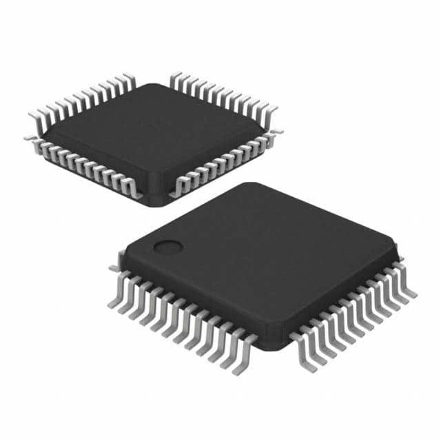
The MSP430F413IPMR is supplied in a 64-pin Low-Profile Quad Flat Package (LQFP-64), identified by the PM package drawing.
| Package Attribute | Description |
|---|---|
| Package Type | LQFP |
| Package Drawing | PM |
| Pin Count | 64 |
| Body Dimensions | 12mm × 12mm |
| Mounting Type | Surface Mount |
| Package Style | Quad Flat Package |
| Ordering Code | MSP430F413IPMR |
| Packaging | Tape and Reel |
| Standard Package Quantity | 1,000 Pieces |
| Operating Temperature | -40°C to +85°C |
The LQFP-64 package provides 64 external connections for power, ground, GPIO, LCD control, clock, reset and debugging functions.
The compact surface-mount design is suitable for automated PCB assembly and embedded products requiring multiple display and control connections.
During PCB development, engineers should follow the official mechanical drawing, recommended land pattern and soldering guidelines from Texas Instruments.
Package Design Considerations:
- Verify the 64-pin LQFP footprint.
- Check pin 1 orientation before assembly.
- Provide suitable decoupling capacitors.
- Separate analog and digital supply routing where appropriate.
- Follow the recommended soldering and PCB layout guidelines.
05. Pinout
The MSP430F413IPMR uses a 64-pin LQFP package. Its pin configuration includes digital I/O, LCD segment outputs, clock connections, power pins, reset and JTAG debugging signals.
Main Pin Groups:
| Pin Group | Function |
|---|---|
| P1.0–P1.7 | General-purpose I/O, timer and comparator functions |
| P2.0–P2.7 | General-purpose I/O, timer, comparator and LCD segment functions |
| P3.0–P3.7 | General-purpose I/O and LCD segment outputs |
| P4.0–P4.7 | General-purpose I/O and LCD segment outputs |
| P5.0–P5.7 | General-purpose I/O and LCD segment/COM connections |
| P6.0–P6.7 | General-purpose I/O connections |
| XIN / XOUT | External oscillator connections |
| RST/NMI | Reset and non-maskable interrupt input |
| TCK / TMS | JTAG debugging signals |
| TDI/TCLK / TDO | JTAG data and clock signals |
| DVCC / DVSS | Digital power supply and ground |
| AVCC / AVSS | Analog power supply and ground |
Selected Physical Pin Assignments:
| Physical Pin | Signal |
|---|---|
| 1 | DVCC |
| 8 | XIN |
| 9 | XOUT |
| 12 | P5.1/S0 |
| 13 | P5.0/S1 |
| 36 | COM0 |
| 37 | P5.2/COM1 |
| 38 | P5.3/COM2 |
| 39 | P5.4/COM3 |
| 54 | TDO |
| 57 | TCK |
| 58 | RST/NMI |
| 62 | AVSS |
| 63 | DVSS |
| 64 | AVCC |
Important Pin Functions:
GPIO: Ports P1 through P6 provide digital input and output capabilities for external sensors, switches and control signals.
LCD Segment Pins: The S0–S23 segment outputs and COM0–COM3 common connections support the integrated multiplexed LCD driver.
XIN and XOUT: These pins connect to an external oscillator when an external clock source is required.
RST/NMI: Provides hardware reset and non-maskable interrupt functionality.
JTAG: The TCK, TMS, TDI/TCLK and TDO signals support debugging and programming operations.
Power Connections: DVCC, DVSS, AVCC and AVSS provide the digital and analog power connections required for correct operation.
PCB Design Recommendations:
- Follow the official pin assignment diagram.
- Connect all required supply and ground pins.
- Use appropriate bypass capacitors near the power pins.
- Keep oscillator connections short and properly routed.
- Verify LCD segment and common assignments.
- Configure unused pins according to TI recommendations.
- Protect programming and debugging connections during PCB development.
06. Specifications
The following table summarizes the principal technical specifications of the MSP430F413IPMR.
| Parameter | Specification |
|---|---|
| Manufacturer | Texas Instruments |
| Part Number | MSP430F413IPMR |
| Product Family | MSP430x4xx |
| Core Architecture | 16-Bit RISC |
| Maximum CPU Frequency | 8MHz |
| Instruction Cycle Time | 125ns |
| Flash Memory | 8KB + 256 Bytes |
| RAM | 256 Bytes |
| Supply Voltage | 1.8V to 3.6V |
| Active Current | 200µA at 1MHz, 2.2V |
| Standby Current | 0.7µA |
| Off Mode Current | 0.1µA with RAM Retention |
| Power-Saving Modes | 5 |
| Wake-Up Time | Less Than 6µs |
| LCD Driver | Up to 96 Segments |
| Timer | 16-Bit Timer_A3 |
| Comparator | Comparator_A |
| Watchdog Timer | 15/16-Bit |
| GPIO | 48 |
| Oscillator | FLL+ / DCO |
| Debug Interface | JTAG |
| Package | LQFP-64 |
| Package Drawing | PM |
| Operating Temperature | -40°C to +85°C |
Processing Performance
The integrated 16-bit RISC CPU operates at up to 8MHz and provides efficient processing for measurement, monitoring and low-speed control applications.
Memory Architecture
The device integrates 8KB Flash memory plus 256 bytes and 256 bytes of RAM. This memory configuration is intended for compact embedded programs and low-resource applications.
Low-Power Performance
The MSP430F413IPMR supports five power-saving modes. TI specifies typical active current of 200µA at 1MHz and 2.2V, standby current of 0.7µA and off-mode current of 0.1µA with RAM retention under the stated conditions.
LCD Control Capability
The integrated LCD driver supports up to 96 segments, making the device useful for display-oriented measurement equipment and handheld electronic instruments.
Timing and Analog Functions
Timer_A3 and Comparator_A support timing, pulse measurement and analog threshold detection. These integrated peripherals reduce the need for external components in compatible circuit designs.
Official Datasheet:
07. Equivalent
When searching for an MSP430F413IPMR equivalent or replacement, engineers should compare CPU architecture, memory capacity, LCD driver functions, peripheral configuration, package dimensions and pin assignments.
The MSP430x41x family includes several related microcontrollers with different memory sizes and peripheral configurations.
| Part Number | Flash / ROM | RAM | Relationship |
|---|---|---|---|
| MSP430F412 | 4KB + 256B Flash | 256B | Related family member |
| MSP430F413 | 8KB + 256B Flash | 256B | Original device family |
| MSP430F415 | 16KB + 256B Flash | 512B | Higher memory variant |
| MSP430F417 | 32KB + 256B Flash | 1KB | Higher memory variant |
| MSP430C413 | 8KB ROM | 256B | Related ROM-based device |
Package Alternatives:
- MSP430F413IPMR: 64-pin LQFP package, tape-and-reel ordering.
- MSP430F413IPM: 64-pin LQFP package, tray ordering.
- MSP430F413IRTDR: 64-pin VQFN package, tape-and-reel ordering.
- MSP430F413IRTDT: 64-pin VQFN package, tape-and-reel ordering with a different quantity configuration.
The LQFP and VQFN versions belong to the same MSP430F413 device family but use different physical package configurations. They should not be assumed to be mechanically interchangeable.
Replacement Selection Checklist:
- Verify the MSP430 16-bit CPU architecture.
- Compare Flash memory and RAM capacity.
- Confirm the 96-segment LCD driver requirement.
- Check Timer_A and Comparator_A functionality.
- Verify the 1.8V to 3.6V operating voltage.
- Compare GPIO availability and alternate functions.
- Check physical pin assignments and package dimensions.
- Review firmware and programming compatibility.
- Verify operating temperature requirements.
Important Replacement Notice:
Related MSP430 family members are not automatically pin-to-pin or firmware-compatible replacements. Differences in memory size, timers, peripheral availability and package configuration must be evaluated before substitution.
08. Manufacturer
The MSP430F413IPMR is manufactured by Texas Instruments (TI), a global semiconductor company specializing in analog and embedded processing technologies.
Texas Instruments develops microcontrollers, power management devices, analog integrated circuits, interface products and semiconductor solutions for industrial, automotive, consumer and communications markets.
The MSP430 family is particularly known for its ultra-low-power architecture and applications involving portable measurement equipment, battery-operated systems and embedded control.
The MSP430F413IPMR combines the MSP430 16-bit CPU with integrated Flash memory, RAM, LCD control, timers and analog comparison functions.
Manufacturer Information:
- Manufacturer: Texas Instruments
- Part Number: MSP430F413IPMR
- Product Family: MSP430x4xx
- Device Category: Microcontroller
- Core: MSP430 16-Bit RISC
- Maximum Frequency: 8MHz
- Flash Memory: 8KB + 256 Bytes
- LCD Driver: 96 Segments
- Package: LQFP-64
- Operating Temperature: -40°C to +85°C
- Product Status: Active
- Official Website: www.ti.com
- Product Page: MSP430F413IPMR Product Information
- Datasheet: MSP430x41x Datasheet PDF
Texas Instruments provides official datasheets, technical documentation and development resources to support engineers working with MSP430-based embedded systems.
For purchasing and component verification, buyers should confirm the exact ordering code, package type, date code, product marking and manufacturer traceability.
09. Applications
The MSP430F413IPMR is designed for low-power embedded systems that require efficient measurement processing, LCD display control and basic analog monitoring.
1. Industrial Meters
The integrated timer, comparator and LCD driver make the device suitable for selected industrial meter designs requiring measurement and display functions.
2. Handheld Measurement Instruments
Its low-power architecture and integrated display controller support handheld instruments where battery life and compact design are important.
3. Electronic Counters
Timer_A3 and GPIO interfaces can support pulse counting, event timing and counter-based electronic systems.
4. Sensor Systems
The integrated comparator and digital processing capabilities support sensor monitoring systems that detect analog thresholds and process measurement signals.
5. Portable Measurement Equipment
The five low-power modes help extend battery operating time in portable measurement products.
6. LCD-Based Electronic Devices
The integrated 96-segment LCD driver makes the MCU suitable for electronic devices requiring segmented displays, numerical readings and status indicators.
7. Battery-Powered Instruments
The low active and standby current characteristics support selected battery-operated electronic instruments.
8. Embedded Monitoring Systems
The GPIO, timer and comparator peripherals provide basic monitoring and control capabilities for compact embedded products.
9. Digital Measurement Controllers
The MSP430F413IPMR can be used in measurement equipment that captures external signals, processes data and presents results through an LCD interface.
10. Low-Power Industrial Control
For applications with moderate processing requirements, the device provides a compact microcontroller platform for timing, threshold detection and display management.
Application Design Recommendations:
- Verify the supply voltage and power consumption requirements.
- Configure the appropriate low-power operating mode.
- Check LCD segment and common connections.
- Use the correct external clock configuration when required.
- Configure Timer_A for the required timing functions.
- Review Comparator_A input requirements.
- Provide suitable power-supply decoupling.
- Follow the official JTAG programming recommendations.
- Consider memory limitations when developing firmware.
- Validate battery life under actual application conditions.
The MSP430F413IPMR is particularly suitable for applications where low power consumption, integrated LCD control and simple measurement processing are more important than high computing performance.
10. Disclaimer
This MSP430F413IPMR technical guide is provided for general electronic component research, engineering reference and product selection purposes.
Technical characteristics are based on publicly available Texas Instruments product information and the official MSP430x41x datasheet.
Actual device performance and current consumption depend on supply voltage, clock configuration, operating mode, peripheral activity and environmental conditions.
Pin assignments and package dimensions should be verified against the official documentation for the exact ordering code before PCB development.
Potential equivalents and replacement microcontrollers must be independently evaluated for electrical, mechanical, memory and firmware compatibility.
Product availability, pricing and ordering information may change. Buyers should confirm the latest information directly with Texas Instruments or authorized distributors.
Official Technical References:
Texas Instruments MSP430F413IPMR Product Page
MSP430x41x Official Datasheet PDF
Editorial Note: This article is an independent technical overview intended to support electronic component research and engineering decisions. It is not an official Texas Instruments publication or a guarantee of component availability, interchangeability or suitability for a specific application.

