


TCA9539PWR Texas Instruments | 16-Bit I2C GPIO Expander
Product Technical Guide TCA9539PWR 16-Bit I2C GPIO Expander Technical GuideTexas Instruments low-voltage 16-bit I2C and SMBus I/O expander featuring a 1.65V to 5.5V supply range, 400kHz Fast-mode opera…
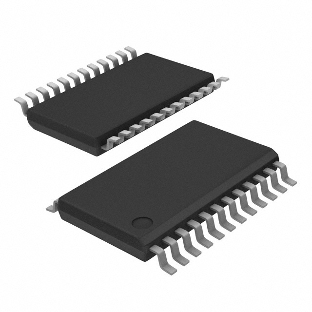
- Part No.:
- TCA9539PWR
- Manufacturer:
- Texas Instruments
- Package:
- 24-TSSOP (0.173", 4.40mm Width)
- Datasheet:
- TCA9539PWR.pdf
- Description:
- IC XPND 400KHZ I2C SMBUS 24TSSOP
- Quantity:
-
Original Supply
Strict supplier screening and quality control support.
-
Datasheet Support
Help engineers quickly verify product specifications.
-
BOM Sourcing
Support multi-part procurement and RFQ matching.
TCA9539PWR Texas Instruments | 16-Bit I2C GPIO Expander
Texas Instruments low-voltage 16-bit I2C and SMBus I/O expander featuring a 1.65V to 5.5V supply range, 400kHz Fast-mode operation, interrupt output, hardware reset, programmable I/O configuration, and compact 24-pin TSSOP packaging.
Product Introduction
The TCA9539PWR is a 16-bit low-voltage I2C and SMBus general-purpose input/output (GPIO) expander manufactured by Texas Instruments. It enables microcontrollers, embedded processors, and digital control systems to expand their available I/O connections through a two-wire serial communication interface.
The device provides 16 independently configurable GPIO pins organized into two 8-bit ports. Each port supports input and output configuration through internal registers, allowing the host controller to monitor switches, read digital status signals, control LEDs, and manage peripheral enable or reset lines.
The TCA9539 operates over a wide supply voltage range of 1.65V to 5.5V, supporting low-voltage embedded systems and conventional 3.3V or 5V logic environments.
Its I2C interface supports Standard-mode communication at 100kHz and Fast-mode communication at 400kHz, making it compatible with many commonly used microcontrollers and embedded processors.
Two external address-selection pins, A0 and A1, allow up to four TCA9539 devices to operate on the same I2C bus without address conflicts. This arrangement can provide up to 64 additional GPIO connections using four expanders.
The device includes an active-low interrupt output, an active-low hardware reset input, programmable polarity inversion, and input/output configuration registers. These functions help simplify host software and reduce the need for dedicated MCU GPIO pins.
The TCA9539PWR is supplied in a 24-pin TSSOP (PW) package and is specified for an operating temperature range of -40°C to +85°C.
Its combination of flexible I/O expansion, low standby power consumption, and compact packaging makes it suitable for industrial control systems, embedded electronics, communication equipment, and digital interface applications.
Key Benefits
16-Bit GPIO Expansion
Adds 16 configurable digital input/output connections while using only the host controller's I2C interface.
Wide Supply Voltage
Supports operation from 1.65V to 5.5V for integration into low-voltage and standard embedded logic systems.
Interrupt and Reset
Provides an active-low interrupt output for input changes and a hardware reset pin for restoring default device configuration.
Flexible Configuration
Programmable input/output direction and polarity inversion registers simplify peripheral control and digital signal monitoring.
Features
- 16-bit general-purpose I/O expansion through I2C or SMBus
- 1.65V to 5.5V operating supply voltage range
- Two independently managed 8-bit GPIO ports
- 100kHz I2C Standard-mode operation
- 400kHz I2C Fast-mode operation
- 16 programmable digital input/output pins
- 5V-tolerant GPIO input capability within specified limits
- Active-low open-drain interrupt output
- Active-low hardware reset input
- Programmable polarity inversion registers
- Input and output configuration registers
- Internal power-on reset
- Glitch-free output behavior during power-up under specified conditions
- Noise filtering on SDA and SCL inputs
- Two hardware address-selection pins
- Four selectable I2C slave addresses
- Low standby-current consumption
- Latched push-pull GPIO outputs
- Output drive capability suitable for certain LED-control applications
- Operating temperature range from -40°C to +85°C
- 24-pin TSSOP surface-mount package
- RoHS and REACH compliance according to TI ordering information
- Tape-and-reel packaging for automated assembly
Design Note: The TCA9539PWR is a digital GPIO expander, not an analog-to-digital converter or a general-purpose level translator. Its I/O pins must be configured and operated within the electrical limits defined in the manufacturer's datasheet.
Package
The TCA9539PWR uses the Texas Instruments PW TSSOP-24 package, a compact surface-mount package with 24 external leads.
- Package Type: TSSOP
- Package Code: PW
- Pin Count: 24
- Mounting Type: Surface Mount
- Approximate Package Dimensions: 7.8mm × 6.4mm overall footprint
- Ordering Suffix: R, tape-and-reel packaging
- Standard Reel Quantity: 2,000 pieces
- Moisture Sensitivity: MSL 1
- Peak Reflow Temperature: 260°C
- Lead Finish: NiPdAu
- Device Marking: PW539
- RoHS Compliance: Yes
- REACH Compliance: Yes
The TSSOP-24 package supports high-density PCB layouts while providing accessible leads for manufacturing inspection and assembly.
For reliable operation, a suitable bypass capacitor should be placed close to the VCC and GND terminals. The I2C signal traces should also be routed with appropriate pull-up resistors and controlled bus capacitance.
PCB designers should use the official Texas Instruments PW package drawing and recommended land pattern rather than relying on generic TSSOP dimensions alone.
Pinout
The TCA9539PWR pinout contains 16 configurable GPIO connections, two I2C interface pins, two address-selection inputs, an interrupt output, a reset input, and power connections.
| Pin | Signal | Function |
|---|---|---|
| 1 | INT | Active-low open-drain interrupt output indicating changes on configured input ports. |
| 2 | A1 | I2C slave-address selection input. |
| 3 | RESET | Active-low hardware reset input. |
| 4 | P00 | Port 0, bit 0 configurable GPIO. |
| 5 | P01 | Port 0, bit 1 configurable GPIO. |
| 6 | P02 | Port 0, bit 2 configurable GPIO. |
| 7 | P03 | Port 0, bit 3 configurable GPIO. |
| 8 | P04 | Port 0, bit 4 configurable GPIO. |
| 9 | P05 | Port 0, bit 5 configurable GPIO. |
| 10 | P06 | Port 0, bit 6 configurable GPIO. |
| 11 | P07 | Port 0, bit 7 configurable GPIO. |
| 12 | GND | Ground reference connection. |
| 13 | P10 | Port 1, bit 0 configurable GPIO. |
| 14 | P11 | Port 1, bit 1 configurable GPIO. |
| 15 | P12 | Port 1, bit 2 configurable GPIO. |
| 16 | P13 | Port 1, bit 3 configurable GPIO. |
| 17 | P14 | Port 1, bit 4 configurable GPIO. |
| 18 | P15 | Port 1, bit 5 configurable GPIO. |
| 19 | P16 | Port 1, bit 6 configurable GPIO. |
| 20 | P17 | Port 1, bit 7 configurable GPIO. |
| 21 | A0 | I2C slave-address selection input. |
| 22 | SCL | I2C serial clock input. |
| 23 | SDA | I2C bidirectional serial data connection. |
| 24 | VCC | Device power supply, 1.65V to 5.5V. |
Important: These pin assignments apply to the 24-pin PW TSSOP package. The TCA9539 QFN package options use different physical pin assignments.
All GPIO pins default to inputs after power-on reset. Configure the required input/output directions before using the pins to control external loads.
Specifications
| Parameter | Value |
|---|---|
| Part Number | TCA9539PWR |
| Manufacturer | Texas Instruments |
| Product Family | TCA9539 |
| Device Type | 16-Bit I2C / SMBus I/O Expander |
| Number of GPIO Pins | 16 |
| GPIO Organization | Two 8-bit ports |
| Supply Voltage Range | 1.65V to 5.5V |
| Communication Interface | I2C / SMBus |
| I2C Standard-Mode Frequency | 100kHz |
| I2C Fast-Mode Frequency | 400kHz |
| Maximum I2C Clock Frequency | 0.4MHz |
| Number of Hardware Address Pins | 2 |
| Selectable I2C Addresses | 4 |
| 7-Bit I2C Address Range | 0x74 to 0x77 |
| GPIO Input Voltage Tolerance | Up to 5.5V within specified limits |
| Interrupt Output | Active-Low Open-Drain |
| Hardware Reset | Active-Low RESET Input |
| Power-On Reset | Integrated |
| GPIO Configuration | Programmable Input / Output |
| Polarity Inversion | Programmable |
| GPIO Output Structure | Push-Pull |
| Maximum GPIO Sink Current | 25mA per pin under specified conditions and aggregate limits |
| Maximum GPIO Source Current | 10mA per pin under specified conditions and aggregate limits |
| Standby Current | 0.9µA typical at 3.6V, with inputs high and no load |
| Operating Temperature Range | -40°C to +85°C |
| Package Type | TSSOP |
| Package Code | PW |
| Pin Count | 24 |
| Mounting Type | Surface Mount |
| Standard Reel Quantity | 2,000 |
| Device Marking | PW539 |
| Moisture Sensitivity Level | MSL 1 |
| RoHS Compliance | Yes |
| REACH Compliance | Yes |
| Product Status | ACTIVE |
I2C Address Configuration: The 7-bit slave address is determined by the logic levels applied to A1 and A0. The supported address range is 0x74 to 0x77.
GPIO Configuration: Each GPIO pin is configured through the device's configuration registers. A logic 1 in a configuration bit selects input operation, while a logic 0 selects output operation.
Interrupt Behavior: The active-low INT output is asserted when an enabled input port changes state relative to the relevant input register comparison. The host can use this signal to identify input activity without continuously polling every GPIO.
Output Drive Consideration: The maximum current capability depends on supply voltage, output voltage, junction temperature, and total port loading. Each GPIO and the combined device output currents must remain within the manufacturer's limits.
Power Consumption: Standby current depends on supply voltage, input levels, and operating conditions. External pull-up resistors and connected loads can contribute additional system-level current consumption.
PCB Design Consideration: I2C pull-up resistor values should be selected based on bus capacitance, supply voltage, and required communication speed.
Equivalent
When evaluating a TCA9539PWR equivalent, replacement, or alternative, compare the I2C address range, GPIO register map, operating voltage, package, pinout, interrupt behavior, reset functionality, and electrical limits.
TCA9539PWRG4: A related Texas Instruments ordering option using the same 24-pin PW package. Confirm current ordering information and applicable manufacturing documentation.
TCA9539RGER: The same TCA9539 functional family in a 24-pin VQFN package. It is suitable for PCB redesigns requiring a smaller package, but it is not footprint-compatible with the TSSOP-24 version.
TCAL9539: An enhanced Texas Instruments 16-bit I2C GPIO expander with additional agile I/O configuration capabilities. TI identifies it as pin-for-pin with the same core functionality. Its extended features and software behavior should be reviewed before substitution.
PCA9539PWR: A related 16-bit I2C I/O expander with a 2.3V to 5.5V supply range. Texas Instruments identifies TCA9539PWR as an upgraded replacement for PCA9539PWR. The older PCA9539 is not recommended for new designs.
TCA9555: Another 16-bit I2C GPIO expander that may be considered for alternative designs. It has different device features and interface behavior; it should not be assumed to be a direct replacement.
Replacement Recommendation: For existing TCA9539PWR PCB assemblies, prioritize the original ordering number or a confirmed compatible ordering variant. Validate physical pinout, I2C addresses, register behavior, operating voltage, and output drive capability before approving another device.
Manufacturer
Texas Instruments Incorporated (TI) is a semiconductor manufacturer specializing in analog integrated circuits, embedded processing, power management, and interface technologies.
The company's interface portfolio includes I2C switches, multiplexers, GPIO expanders, voltage-level translators, communication transceivers, and other devices used in embedded electronic systems.
The TCA9539 series provides a flexible method for expanding digital I/O resources without requiring additional dedicated GPIO pins on the host processor.
Official Product Page: TCA9539PWR – Texas Instruments
Official Datasheet: TCA9539 Low-Voltage 16-Bit I2C / SMBus I/O Expander Datasheet
Manufacturer Website: www.ti.com
For procurement, confirm the complete ordering part number, original manufacturer, packaging quantity, lot and date codes, and traceability documentation.
Applications
Industrial Control Systems
Expansion of digital inputs and outputs for industrial controllers, equipment interfaces, and automation modules.
Embedded Systems
Additional GPIO resources for microcontroller-based designs with limited available I/O pins.
LED and Indicator Control
Programmable digital outputs for status LEDs, indicator signals, and suitable low-current loads.
Switch and Button Monitoring
Digital input expansion for switches, push-buttons, and control-panel status signals.
Communication Equipment
Peripheral reset, enable, alarm, and status-signal management in networking and communication hardware.
System Control Interfaces
Management of enable signals, hardware resets, fan-control logic, and digital peripheral interfaces.
Application Note: In a typical embedded design, the host MCU communicates with the TCA9539PWR through SDA and SCL. External pull-up resistors are required on the I2C bus, and the INT output requires a pull-up if used. The A0 and A1 pins determine the slave address, while RESET can be connected to the host or held inactive through a suitable pull-up.
For LED loads, external drivers or current-limiting components may be necessary depending on the required current. For inductive loads such as relays or motors, appropriate external driver and protection circuits must be used rather than connecting the load directly to a GPIO pin.
Disclaimer
This technical guide is provided for general product identification, engineering reference, and procurement support. All specifications, I2C address assignments, pin configurations, operating conditions, current limits, package dimensions, environmental compliance information, and lifecycle status should be verified against the latest Texas Instruments documentation before design or purchase. Suggested alternatives are not guaranteed direct replacements. Product prices and availability may change without notice.

