

Understanding series parallel circuit total resistance is one of the most useful skills in basic electrical and electronics engineering. Real circuits are rarely made from only one resistor connected in a simple line or only several resistors connected in parallel. Instead, many practical circuits contain a mixture of series and parallel branches. To find how much resistance the complete circuit presents to a power source, you need to reduce the circuit step by step.
理解串联并联电路总电阻是基础电气和电子工程中最有用的技能之一.真实电路很少仅由一个电阻组成简单线路,也很少仅由多个电阻并联组成.相反,许多实际电路包含串联和并联分支的混合.要计算整个电路对电源的电阻,你需要逐步降低电路的阻抗.
The good news is that the basic idea is much simpler than the terminology suggests. Whether a circuit is powered by a battery, DC adapter, solar panel, generator, or another electrical source, the same resistance principles can help you understand current flow, voltage distribution, and power consumption.
好消息是,这个基本概念比术语所暗示的要简单得多.无论电路是由电池\直流适配器\太阳能电池板\发电机还是其他电源供电,相同的电阻原理都能帮助你理解电流流动\电压分布和功耗.
This guide explains series parallel circuit total resistance in plain English and connects the topic with several closely related electrical concepts, including direct current, dc current, dc power, what is dc, direct current vs ac, and ac vs dc power. It also explains common voltage symbols, including dc voltage symbol E and the commonly used ac voltage symbol, so you can understand circuit diagrams more confidently.
本指南用通俗易懂的英语解释串联并联电路总电阻,并将该主题与多个密切相关的电气概念联系起来,包括直流电\直流电\直流电\直流电与交流电以及交流电与直流电.它还解释了常见的电压符号,包括直流电压符号 E 和常用的交流电压符号,让你更自信地理解电路图.
What Is Series Parallel Circuit Total Resistance?
什么是串联并联电路总电阻?
Series parallel circuit total resistance means the equivalent resistance of a circuit that contains both series-connected and parallel-connected resistors. Instead of treating every resistor independently, we replace groups of resistors with one equivalent resistance until the entire circuit can be represented by a single resistance value.
串联并联电路总电阻是指包含串联和并联连接电阻的电路的等效电阻.我们不是单独处理每个电阻,而是用一个等效电阻替换电阻组,直到整个电路能用单一电阻值表示.
The final value is commonly called total resistance, equivalent resistance, or effective resistance. It tells us how strongly the complete resistor network opposes current from the power source.
最终的值通常被称为总电阻\等效电阻或有效电阻.它代表了整个电阻网络对电流流动的阻碍程度.
For example, imagine a 10 Ω resistor connected in series with a branch containing two resistors of 20 Ω and 30 Ω in parallel. The two parallel resistors can first be replaced with their equivalent resistance. That result is then added to the 10 Ω series resistor.
例如,想象有一个 10 欧姆的电阻器与另一个电路串联在一起,而这个电路中还有两个并联的电阻器,分别为 20 欧姆和 30 欧姆.这两个并联的电阻器可以先用它们的等效电阻来替代.然后将这个等效电阻加上 10 欧姆的串联电阻器.
This step-by-step reduction is the key to solving almost every basic mixed-resistance problem.
这种逐步简化的方法几乎是解决几乎所有基本混合电阻问题的关键.
Why Total Resistance Matters
Resistance is not just a number used in mathematics. It directly affects the amount of current flowing through a circuit. According to Ohm's law:
V = I × R
Where:
- V is voltage in volts (V).
- I is current in amperes (A).
- R is resistance in ohms (Ω).
Once you know the total resistance, you can calculate the total current when the supply voltage is known:
I = V / R
This is especially important in DC current circuits. If the total resistance becomes smaller while the supply voltage remains unchanged, the current generally becomes larger. If total resistance increases, the current decreases.
Knowing the resistance also helps engineers estimate voltage drops, resistor power ratings, battery loading, heat generation, and whether components are operating within safe limits.
Series Resistance: The Simplest Case
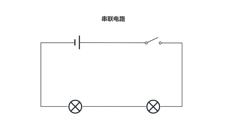
Before solving a mixed circuit, it is important to understand a pure series circuit.
When resistors are connected in series, there is only one path for current. Therefore, the same current passes through every resistor.
The total resistance is simply:
RT = R1 + R2 + R3 + ... + Rn
For example, suppose a circuit contains three resistors:
- R1 = 10 Ω
- R2 = 20 Ω
- R3 = 30 Ω
The total resistance is:
RT = 10 + 20 + 30 = 60 Ω
A useful rule is that the total resistance of series resistors is always greater than any individual resistor in that series group.
Parallel Resistance: Multiple Paths for Current
Parallel circuits are different because current has more than one path to follow. Each parallel resistor is connected across the same two electrical nodes, so the voltage across each resistor is the same.
For two resistors in parallel, the formula is:
RT = (R1 × R2) / (R1 + R2)
For example, if R1 = 20 Ω and R2 = 30 Ω:
RT = (20 × 30) / (20 + 30) = 600 / 50 = 12 Ω
Notice something important: 12 Ω is smaller than both 20 Ω and 30 Ω. This is a fundamental characteristic of parallel resistors.
For three or more parallel resistors, use the reciprocal formula:
1 / RT = 1 / R1 + 1 / R2 + 1 / R3 + ... + 1 / Rn
When several resistors are placed in parallel, adding another branch normally decreases the equivalent resistance because the circuit provides another path for current.
How to Calculate Series Parallel Circuit Total Resistance
The most reliable method is to simplify the circuit from the inside outward. Do not try to combine every resistor at once. Instead, identify groups that are clearly in series or clearly in parallel.
- Identify the simplest series or parallel resistor group.
- Calculate the equivalent resistance of that group.
- Replace the group with a single equivalent resistor.
- Look at the simplified circuit again.
- Repeat the process until only one total resistance remains.
This approach makes a complicated resistor network much easier to understand.
Series Parallel Circuit Total Resistance Example
Consider a circuit with a 10 Ω resistor in series with two parallel resistors: 20 Ω and 30 Ω.
First calculate the parallel section:
RP = (20 × 30) / (20 + 30) = 12 Ω
Now the circuit has only two series resistances: 10 Ω and 12 Ω.
Therefore:
RT = 10 + 12 = 22 Ω
So the series parallel circuit total resistance is 22 Ω.
This example demonstrates the basic strategy: solve the parallel portion first, then combine the result with the series portion.
A More Complex Mixed Resistance Example
Now consider a circuit containing a 5 Ω resistor in series with a parallel network. The parallel network contains a 10 Ω resistor in one branch and two series resistors of 15 Ω and 25 Ω in another branch.
First simplify the series branch:
15 Ω + 25 Ω = 40 Ω
The parallel network is now made from 10 Ω and 40 Ω:
RP = (10 × 40) / (10 + 40) = 400 / 50 = 8 Ω
Finally, add the 5 Ω series resistor:
RT = 5 + 8 = 13 Ω
The total resistance is therefore 13 Ω.
The important lesson is not just the answer. The important lesson is the order of calculation. A series resistor inside a parallel branch must be combined first before the parallel calculation is performed.
What Is DC?
If you are learning resistance calculations, you will quickly encounter the question: what is dc?
DC means direct current. In a simplified explanation, direct current is electrical current that flows in one direction. Batteries are a familiar example of a DC source. Many electronic circuits also operate internally using DC voltage and DC current, even when the equipment is ultimately connected to an AC wall outlet.
A DC waveform can be constant, such as a battery's nominal output, or it can vary over time while maintaining the same overall direction. Therefore, DC does not always mean perfectly flat voltage.
Common direct current power sources include batteries, USB power supplies, solar cells, DC adapters, and regulated power supplies. The phrase direct current power sour sometimes appears in incomplete keyword searches; the more natural technical term is direct current power source.
Direct Current and DC Current
Direct current describes the type of current flow, while DC current is the commonly used phrase for the actual current flowing in a DC circuit.
For a simple resistive DC circuit, Ohm's law is straightforward. If a 12 V DC power source is connected to a 24 Ω resistor:
I = V / R = 12 / 24 = 0.5 A
The circuit therefore draws 0.5 A under the assumed conditions.
If the resistor network has multiple series and parallel sections, you can first calculate the series parallel circuit total resistance and then use the total resistance to find the source current.
Understanding DC Power
DC power describes electrical power delivered or consumed in a direct-current circuit. For a resistive load, the basic power equation is:
P = V × I
Using Ohm's law, power can also be calculated as:
P = I²R
or:
P = V²/R
For example, a 12 V source connected to a 24 Ω resistor draws 0.5 A. The resistor consumes:
P = 12 × 0.5 = 6 W
This explains why total resistance matters beyond simply calculating current. A change in resistance can also change the power consumed by a circuit.
DC Voltage Symbol E: What Does E Mean?
The phrase dc voltage symbol E needs a little clarification because electrical notation is not completely uniform across textbooks and industries.
The letter V is commonly used to represent voltage. The letter E is often used for electromotive force (EMF) or source voltage. In some circuit-analysis contexts, E can therefore represent the voltage supplied by a source such as a battery.
For example, a simple circuit may be described using:
E = 12 V
where E represents the source electromotive force.
It is more accurate to say that E can represent source EMF rather than claiming that E is the universal DC voltage symbol. Different circuit diagrams may use V, E, or other notation depending on the application and convention.
What Is the AC Voltage Symbol?
The ac voltage symbol is commonly shown using a tilde, such as V~, or through an AC waveform symbol. The exact representation depends on the schematic standard and the equipment manufacturer.
AC means alternating current. Unlike direct current, alternating current periodically changes direction. Household electrical systems are common examples of AC power.
This distinction becomes important when comparing circuit behavior, power supplies, transformers, motors, and measurement instruments.
Direct Current vs AC
The basic difference between direct current vs ac is the direction of current flow.
- DC: Current flows in one primary direction.
- AC: Current periodically changes direction.
- DC sources: Batteries, solar cells, and many electronic power supplies.
- AC sources: Utility grids and many generators.
In a DC resistive circuit, the voltage and current can often be analyzed using relatively simple constant-value equations. AC circuits may require additional concepts such as frequency, phase, reactance, and impedance, especially when capacitors and inductors are involved.
AC vs DC Power: Why the Difference Matters
The phrase ac vs dc power is often used when discussing electrical distribution and electronic equipment. Both AC and DC can deliver useful electrical power, but they are used differently.
AC is widely used for power distribution because voltage can be changed efficiently with transformers. DC is especially important inside modern electronic equipment because integrated circuits, microcontrollers, sensors, memory devices, and many other semiconductor components typically require DC supply rails.
A desktop computer, for example, may receive AC power from a wall outlet but internally convert it into several DC voltage levels. A smartphone charger works in a similar general way: it accepts an AC input and provides a controlled DC output.
Therefore, the real-world question is often not simply whether AC or DC is better. It is which type of electrical power is appropriate for a particular stage of the system.
Does Series Parallel Circuit Total Resistance Change Between AC and DC?
For an ideal network containing only ordinary resistors, the basic resistance formulas are the same for AC and DC. Two resistors in series are still added, and parallel resistors still follow the reciprocal relationship.
However, real circuits may contain capacitors, inductors, transformers, motors, filters, and other frequency-dependent components. In these circuits, simply adding resistance values may not fully describe the circuit's behavior under AC conditions.
For AC analysis, engineers often use impedance rather than resistance alone. Impedance includes both resistance and reactance and can change with frequency.
This creates an important practical distinction: series parallel circuit total resistance is sufficient for purely resistive networks, but more advanced AC networks may require series-parallel impedance calculations.
How Voltage and Current Behave in Series and Parallel Circuits
One of the easiest ways to remember series and parallel behavior is to focus on what stays the same.
Series Circuits
In a simple series circuit:
- The same current flows through each component.
- The supply voltage is divided among the components.
- Total resistance is the sum of the individual resistances.
The voltage drop across an individual resistor is:
VR = I × R
Parallel Circuits
In a simple parallel circuit:
- The voltage across each branch is the same.
- The total current is divided among the branches.
- The equivalent resistance is lower than the smallest individual branch resistance.
For a parallel resistor, branch current can be calculated using:
Ibranch = V / Rbranch
These two rules are extremely useful when checking whether a calculated answer makes sense.
How to Check Your Total Resistance Answer
A good circuit calculation should always pass a basic reality check.
For resistors in series, the total resistance must be larger than each individual resistor in that series group.
For resistors in parallel, the equivalent resistance must be smaller than the smallest resistor in the parallel group.
If your result violates these rules, there is a good chance that a resistor was grouped incorrectly or a mathematical error occurred.
Another useful check is to calculate source current after finding the total resistance. If a 12 V source is connected to a 100 Ω equivalent load, the current should be approximately 0.12 A. If your calculation produces 12 A, the result clearly deserves another look.
Common Mistakes When Calculating Mixed Resistance
Adding Parallel Resistors Directly
A common beginner mistake is to calculate two 10 Ω resistors in parallel as 20 Ω. This is incorrect. Two identical 10 Ω resistors in parallel produce an equivalent resistance of 5 Ω.
Using the Parallel Formula on a Series Group
The opposite mistake is also common. If resistors share the same current path and there is no branching between them, they may be in series and should normally be added.
Ignoring Circuit Nodes
The physical appearance of a schematic can sometimes be misleading. Two components may look close together without actually being connected in the same way. Always follow the wires and identify the electrical nodes.
Confusing Resistance With Impedance
Resistance is sufficient for ideal resistor networks. AC circuits containing capacitors and inductors may require impedance instead.
Forgetting Power Ratings
A resistor can have the correct resistance value but still fail if its power rating is too low. After finding current and voltage, check the resistor's power dissipation.
Using a Multimeter to Check Resistance
A multimeter is one of the most useful tools for basic electrical troubleshooting. It can commonly measure resistance, DC voltage, DC current, and AC voltage, depending on the model.
When measuring resistance, the circuit should normally be de-energized. Measuring resistance on a powered circuit can produce incorrect readings and may damage the meter.
A practical workflow is:
- Turn off the circuit power.
- Set the multimeter to resistance mode.
- Choose an appropriate resistance range if the meter is not auto-ranging.
- Place the probes across the component or section being tested.
- Compare the measured value with the expected value.
Be careful when measuring resistance inside a larger circuit. Other components connected in parallel can affect the reading, so an in-circuit measurement may not equal the marked value of a single resistor.
Measuring DC Voltage and DC Current
Measuring DC voltage is generally performed by placing the multimeter across two points in the circuit. The meter is connected in parallel with the point being measured.
DC current measurement is different. To measure dc current, the meter must normally become part of the current path. The circuit must therefore be opened and the meter inserted appropriately.
This difference is important because connecting a current meter directly across a voltage source can create a very low-resistance path and potentially cause a short circuit.
Always check the meter's input terminals, measurement category, current limit, and manufacturer's instructions before taking measurements.
Series Parallel Resistance and Electrical Power
Once the total resistance is known, you can connect the resistance calculation to electrical power.
For a DC circuit:
IT = VT / RT
Then:
PT = VT × IT
Combining these equations gives:
PT = VT² / RT
Therefore, a reduction in total resistance can cause the source current to increase significantly when the supply voltage remains fixed. This is one reason why short circuits and unexpectedly low-resistance loads can be dangerous.
Practical Applications of Series Parallel Circuits
Mixed resistor networks appear throughout electronics and electrical systems.
- Voltage divider networks
- Sensor interfaces
- LED circuits
- Battery-powered equipment
- Control panels
- Audio electronics
- Power supply circuits
- Measurement instruments
- Industrial control systems
- Automotive electronics
- Consumer electronic devices
For example, a voltage divider may use two series resistors to produce a lower voltage from a larger DC supply. Additional components may be connected in parallel with one of the resistors, changing the effective resistance and therefore changing the actual output voltage.
This is why understanding series parallel circuit total resistance is more useful than memorizing a single formula. It gives you a method for analyzing how real circuits behave when components are added or removed.
A Simple Strategy for Any Series-Parallel Circuit
When facing an unfamiliar circuit, use the following mental checklist:
- Find the branches. Look for points where the current has more than one path.
- Find obvious series groups. Components connected along one uninterrupted path can often be combined.
- Find obvious parallel groups. Components connected across the same two nodes are candidates for parallel reduction.
- Simplify. Replace each group with its equivalent resistance.
- Repeat. Continue until the entire circuit becomes one resistance.
- Apply Ohm's law. Use the total resistance to calculate source current when the voltage is known.
- Check power. Confirm that the components can safely handle the calculated power.
This method works especially well when studying DC circuits because the relationships among voltage, current, resistance, and power are straightforward.
Quick Formula Reference
For easy reference, the most important equations are:
- Series resistance: RT = R1 + R2 + ...
- Two parallel resistors: RT = (R1 × R2) / (R1 + R2)
- Multiple parallel resistors: 1/RT = 1/R1 + 1/R2 + ...
- Ohm's law: V = I × R
- Current: I = V/R
- Voltage: V = I × R
- DC power: P = V × I
- Power using resistance: P = I²R
- Power using voltage: P = V²/R
Series Parallel Circuit Total Resistance: The Key Idea
The most important idea is simple: do not treat a complicated resistor network as one complicated problem. Break it into small, recognizable groups.
Series resistors are combined by addition. Parallel resistors are combined using the reciprocal relationship or the two-resistor shortcut. After each reduction, look at the remaining circuit and repeat the process.
Once the total resistance is known, the rest of the analysis becomes much easier. You can determine dc current, calculate dc power, estimate voltage drops, and evaluate whether the circuit behaves as expected.
The same foundation also helps when moving from basic DC analysis to more advanced topics such as direct current vs ac, ac vs dc power, impedance, frequency response, and AC circuit analysis.
Conclusion
Learning series parallel circuit total resistance is not simply about remembering two resistance formulas. It is about learning how to read a circuit, recognize electrical relationships, simplify complex networks, and connect resistance with voltage, current, and power.
For DC systems, the process is particularly accessible. A direct current source provides electrical energy, resistance limits current, voltage establishes the electrical potential difference, and power describes the rate at which electrical energy is delivered or consumed.
Understanding what is dc, how dc current behaves, how dc power is calculated, and how direct current vs ac systems differ gives you a stronger foundation for practical electronics. When you add the ability to calculate equivalent resistance, even a complicated series-parallel network becomes much easier to analyze.
Whether you are checking a resistor network with a multimeter, designing a DC-powered electronic circuit, studying AC vs DC power, or learning how voltage and current move through a practical electrical system, the same core principle remains useful: simplify the circuit step by step, calculate the equivalent resistance, and then use Ohm's law and power equations to understand what the circuit is doing.