

If you have ever opened an electronics textbook or searched online for circuit theory, you have probably come across the term series parallel circuit total resistance. At first glance, it may look like a complicated engineering phrase. In reality, the concept is much easier than it sounds.
Most real-world electrical and electronic circuits are not purely series or purely parallel. Instead, they combine both arrangements to perform different functions. Once you understand how to recognize series and parallel sections and how to reduce them step by step, calculating the total resistance of even a fairly complex circuit becomes much more manageable.
This guide explains series parallel circuit total resistance from the ground up. Rather than simply giving you formulas to memorize, we will focus on why the formulas work, how to recognize different circuit configurations, how to simplify a mixed network, and how these principles apply to real electrical systems.
By the end, you should be able to approach a series and parallel circuit with confidence, identify the simplest sections, calculate their equivalent resistance, and gradually reduce the entire network to one final resistance value.
What Are Series and Parallel Circuits?
Before calculating total resistance, it is important to understand the two basic building blocks of electrical circuits: series circuits and parallel circuits.
Almost every complicated resistor network can be understood as a combination of these two fundamental arrangements. Once you can identify them, the calculation becomes a process of simplification rather than a difficult mathematical puzzle.
What Is a Series Circuit?
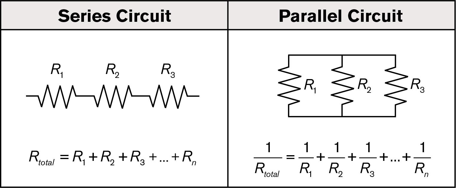
A series circuit is a circuit in which components are connected one after another along a single electrical path. Imagine a single-lane road with several toll booths. Every car has to pass through every toll booth because there is no alternative route.
The same basic idea applies to current in a series circuit. There is only one path available, so the same current flows through every component in that path.
The key characteristics of a series circuit are:
- The same current flows through each component.
- The supply voltage is divided among the components.
- The total resistance increases when additional resistors are added in series.
- If one component becomes an open circuit, the complete current path is interrupted.
A classic example is an old-style string of Christmas lights. If the circuit design places the bulbs in series and one bulb or connection fails open, the current path can be interrupted and the entire string may go out.
What Is a Parallel Circuit?
A parallel circuit provides multiple paths for current to flow. Think of a multi-lane highway. Cars can choose different lanes, but the lanes begin and end at common points.
In an electrical parallel circuit, components are connected between the same two nodes. Because they share the same two electrical points, each branch has the same voltage across it.
The key characteristics of a parallel circuit are:
- The voltage across each parallel branch is the same.
- The total current equals the sum of the currents through all branches.
- Adding another resistive branch normally reduces the equivalent resistance.
- If one branch becomes open, the remaining branches can often continue operating.
This is why many household electrical loads are arranged in parallel. If one appliance stops working, other appliances can normally continue operating independently.
When people search for terms such as circuit and parallel or electricity series and parallel, they are essentially looking for an explanation of how these two fundamental connection methods determine current, voltage, and resistance.
What Is Series Parallel Circuit Total Resistance?
Series parallel circuit total resistance refers to the equivalent resistance of a circuit that contains both series-connected and parallel-connected resistors.
The important thing to understand is that there is usually no single special formula that solves every mixed circuit instantly. Instead, you simplify the network section by section.
Think of the circuit as a puzzle. You do not need to solve the entire puzzle at once. Find the simplest section, replace it with its equivalent resistance, and then look at the circuit again. Continue this process until the entire network has been reduced to one resistance.
The Golden Rule: Simplify From the Inside Out
The most useful strategy for calculating series parallel circuit total resistance is to simplify the circuit from the inside out.
First, identify a group of resistors that is clearly connected in series or clearly connected in parallel. Calculate the equivalent resistance of that group. Then replace the group with a single equivalent resistor.
After that, redraw the circuit if necessary and look for the next simplest section.
This process can be repeated until only one equivalent resistance remains.
Some learners describe this method as an "onion approach." You peel away one layer of the circuit at a time until you reach the center. The terminology is not important; the process is.
The key is to avoid trying to calculate everything simultaneously.
The Two Essential Resistance Formulas
For most basic series and parallel circuits, you only need two fundamental resistance rules.
Formula 1: Series Resistance
When resistors are connected in series, their resistances simply add together:
RTotal = R1 + R2 + R3 + ...
This makes intuitive sense. If current must pass through several resistive elements one after another, each element adds additional opposition to current flow.
For example:
10 Ω + 20 Ω + 30 Ω = 60 Ω
Therefore, three resistors of 10 Ω, 20 Ω, and 30 Ω connected in series have a total resistance of 60 Ω.
Formula 2: Parallel Resistance
For resistors connected in parallel, the general formula is:
1 / RTotal = 1 / R1 + 1 / R2 + 1 / R3 + ...
For two parallel resistors, there is a convenient shortcut:
RTotal = (R1 × R2) / (R1 + R2)
This shortcut is particularly useful when solving basic parallel circuit problems by hand.
There is also an important rule that can help you check your answer: when two or more positive resistances are connected in parallel, their equivalent resistance is always lower than the smallest individual resistance in that parallel group.
If your calculated parallel resistance is higher than the smallest resistor in the group, stop and check your calculation.
Step-by-Step Example of a Mixed Series and Parallel Circuit
Now let's apply the formulas to a practical example of series parallel circuit total resistance.
Imagine a circuit containing:
- R1 = 10 Ω
- R2 = 20 Ω
- R3 = 30 Ω
- R4 = 5 Ω
Suppose R2 and R3 are connected in parallel, while R1 is connected in series before the parallel section and R4 is connected in series after it.
The circuit can therefore be described as:
R1 + (R2 || R3) + R4
Step 1: Find the Simplest Section
R2 and R3 form a parallel block. Since there are only two resistors, we can use the shortcut formula:
R23 = (20 × 30) / (20 + 30)
R23 = 600 / 50 = 12 Ω
Therefore, the 20 Ω and 30 Ω resistors can be replaced by a single 12 Ω equivalent resistor.
Step 2: Redraw the Simplified Circuit
After replacing R2 and R3 with the equivalent 12 Ω resistor, the circuit is now much simpler.
We have three resistive elements connected in series:
R1 = 10 Ω
R23 = 12 Ω
R4 = 5 Ω
Step 3: Add the Series Resistances
Now apply the series resistance formula:
RTotal = 10 Ω + 12 Ω + 5 Ω
RTotal = 27 Ω
Therefore, the series parallel circuit total resistance is:
27 Ω
This example demonstrates the central idea. You do not need to attack the entire mixed network at once. First reduce the parallel section, then treat the simplified section as one resistor and complete the series calculation.
How to Identify a True Parallel Connection
One of the most common mistakes in series and parallel circuits is deciding that components are parallel simply because they look visually parallel on a diagram.
The physical appearance of the drawing is not the deciding factor.
The correct question is:
Do the two components connect between the same two electrical nodes?
If two resistors share both endpoints, they are connected in parallel. If they share only one connection point and the current must pass through one before reaching the other, they are generally in series, assuming there is no additional branching at the intermediate node.
This node-based way of thinking is much more reliable than judging a circuit by its visual shape.
Five Common Mistakes When Calculating Total Resistance
Mistake 1: Confusing Series and Parallel Connections
The first mistake is trying to identify series and parallel relationships based only on how the circuit is drawn.
Instead, follow the actual electrical connections. Ask whether there is one current path or multiple paths, and check whether components share the same two nodes.
Mistake 2: Trying to Solve Everything in One Step
Complex circuits can become confusing when you attempt to calculate every resistor simultaneously.
A much better method is to simplify one section at a time. After every reduction, redraw the circuit. This simple habit makes series parallel circuit total resistance calculations significantly easier.
Mistake 3: Using the Wrong Formula
Keep the basic rules clear:
- Series: Add the resistances directly.
- Parallel: Add the reciprocals, or use the product-over-sum shortcut for two resistors.
Do not add parallel resistors directly unless you are dealing with a special case where that operation is actually appropriate.
Mistake 4: Forgetting the Parallel Resistance Check
For ordinary positive resistors in parallel, the equivalent resistance must be smaller than the smallest resistor in that group.
For example, if 10 Ω and 20 Ω resistors are connected in parallel, the equivalent resistance must be below 10 Ω.
This simple rule is an excellent way to catch arithmetic errors.
Mistake 5: Making a Simple Circuit Too Complicated
Not every circuit needs advanced mathematics. If a circuit contains only a few clearly connected resistors, begin with the basic series and parallel rules.
Ask yourself:
Is there one path for current, or are there multiple paths?
That question often tells you where to start.
Why Series Parallel Resistance Matters in Real Life
Understanding series parallel circuit total resistance is not just an academic exercise. These concepts are fundamental to electrical troubleshooting, circuit design, power management, and electronic engineering.
Household Electrical Systems
Many household loads are connected in parallel so that each device can receive the intended supply voltage and operate independently.
For example, turning on a microwave does not normally cause another properly wired appliance to stop working simply because the two devices are connected to the same electrical system. Instead, each branch draws current according to its own load.
In North America, residential systems commonly use approximately 120 V circuits, while many other regions use approximately 220–240 V supplies. The exact voltage depends on the local electrical system and applicable standards.
The important concept is that parallel branches receive the same nominal supply voltage, while the total current drawn from the source depends on the combined loads.
Automotive Electrical Systems
Vehicles commonly use combinations of series and parallel circuits.
For example, multiple lamps or accessories may be connected as separate branches, while switches, relays, fuses, and protective devices are placed at appropriate points in the circuit.
A typical design may therefore contain a parallel group of loads controlled by a series switching element. This is an example of a parallel circuit in a series circuit arrangement.
Understanding the equivalent resistance and current path can be extremely useful when diagnosing a blown fuse, dim light, voltage drop, or unexpected current draw.
Battery Packs
Batteries provide another useful example of series and parallel concepts.
Connecting battery cells in series increases the overall voltage of the pack, assuming compatible cells and appropriate system design. Connecting cells in parallel can increase available capacity and current capability while maintaining approximately the same nominal voltage.
Modern battery packs are more complicated than this simple explanation because they also involve battery management systems, cell balancing, protection circuits, temperature monitoring, and carefully controlled charging and discharging.
Consumer Electronics
Inside a smartphone, laptop, power supply, or other electronic product, you can find many networks containing series and parallel components.
Engineers use these arrangements to control voltage, current, filtering, signal behavior, power consumption, and heat generation.
Although a simple series resistance calculator can quickly calculate a group of resistors, real circuit design often requires much more than calculating resistance alone. Engineers may also need to consider component tolerance, temperature, frequency, power dissipation, transient behavior, and the characteristics of active devices.
Advanced Insight: Equivalent Resistance as a Black Box
One of the most useful ways to understand equivalent resistance is to think of it as a "black box."
Imagine replacing a complicated network of resistors with one carefully calculated resistor. From the perspective of the rest of the circuit, the simplified network behaves the same way with respect to the relevant voltage-current relationship at its terminals.
This is the power of equivalent resistance.
Instead of analyzing every internal resistor immediately, you can treat the entire network as one component. This approach is fundamental to circuit analysis and helps engineers manage complex electrical networks.
Advanced Insight: Total Resistance Determines Source Current
Once you know the series parallel circuit total resistance, you can use Ohm's law to calculate the total current drawn from a voltage source:
V = I × R
Rearranging the equation gives:
I = V / R
For example, if a simplified circuit has a total resistance of 27 Ω and is connected to a 54 V ideal source:
I = 54 / 27 = 2 A
Once the total current is known, you can continue analyzing the voltage drops across series components and the current distribution between parallel branches.
This is why total resistance is more than just a final number. It provides a starting point for understanding how the entire circuit behaves.
Advanced Insight: Resistor Tolerance Matters
Real-world resistors are not perfectly precise. A resistor labeled 100 Ω may have a tolerance such as ±1%, ±5%, or another specified value.
This means the actual resistance can differ slightly from the nominal value.
When calculating series parallel circuit total resistance for a real product, engineers may need to consider both the minimum and maximum possible resistance values rather than relying only on nominal values.
This becomes especially important in precision circuits, protection systems, measurement equipment, and applications where current or voltage must remain within a narrow range.
Advanced Insight: What Happens During a Short Circuit?
A short circuit is an extreme case in which a very low-resistance path connects two points that should normally have a higher resistance between them.
If an ideal zero-resistance wire is placed directly across a resistor in a simplified circuit model, the equivalent resistance of that parallel combination approaches zero.
As resistance decreases, current can increase dramatically according to Ohm's law. In real systems, the current is also limited by the source, wiring, internal resistance, protection devices, and other factors.
This is why fuses, circuit breakers, current limiting circuits, and other protective mechanisms are essential in practical electrical systems.
Quick Reference: Series Parallel Circuit Total Resistance
| Circuit Type | Calculation Method | Quick Check |
|---|---|---|
| Series Circuit | RTotal = R1 + R2 + R3 + ... | Total resistance is greater than any individual resistor. |
| Parallel Circuit | 1/RTotal = 1/R1 + 1/R2 + ... | Total resistance is lower than the smallest individual resistor. |
| Two Parallel Resistors | RTotal = (R1 × R2) / (R1 + R2) | Use the product-over-sum shortcut. |
| Mixed Series-Parallel Circuit | Simplify the innermost parallel or series sections first. | Work from the inside out. |
A Second Series Parallel Circuit Example
Let's work through another example to reinforce the process.
Suppose a circuit contains:
- R1 = 4 Ω
- R2 = 12 Ω
- R3 = 6 Ω
- R4 = 2 Ω
R2 and R3 are connected in parallel. R1 and R4 are connected in series with this parallel block.
The circuit can therefore be represented as:
R1 + (R2 || R3) + R4
Step 1: Calculate the Parallel Section
Use the two-resistor parallel formula:
R23 = (12 × 6) / (12 + 6)
R23 = 72 / 18 = 4 Ω
So the 12 Ω and 6 Ω resistors are equivalent to a 4 Ω resistor.
Step 2: Add the Series Resistors
Now the circuit contains three series elements:
RTotal = 4 Ω + 4 Ω + 2 Ω
RTotal = 10 Ω
Therefore, the series parallel circuit total resistance is 10 Ω.
Notice an interesting result here: the parallel block of 12 Ω and 6 Ω becomes 4 Ω. Once that block is reduced to a single equivalent resistance, the rest of the calculation is simply a series addition.
When Should You Use a Series Resistance Calculator?
A series resistance calculator can be useful when you need a quick numerical result, especially when a circuit contains many resistors or when decimal values make manual calculations inconvenient.
However, a calculator cannot replace circuit understanding.
The most important step is identifying which components are actually in series and which are actually in parallel. If the circuit topology is interpreted incorrectly, even a perfectly accurate calculator will produce the wrong answer.
A good workflow is therefore:
- Understand the circuit topology.
- Identify the simplest series or parallel group.
- Apply the appropriate formula.
- Replace that group with its equivalent resistance.
- Repeat until one total resistance remains.
- Use a calculator to verify the arithmetic when necessary.
Series Resistance vs. Parallel Resistance
It is useful to understand the fundamental difference between series and parallel resistance at a conceptual level.
In a series connection, every additional resistor adds another obstacle to the same current path. As a result, total resistance increases.
In a parallel connection, every additional resistor creates another path for current. As a result, the equivalent resistance decreases.
This gives you a powerful mental shortcut:
More resistance in series means more total resistance. More conductive paths in parallel mean less total resistance.
This simple idea can help you predict whether a calculated answer makes sense before doing detailed mathematics.
Why the Node Concept Is More Important Than the Drawing
As circuits become more complicated, the visual arrangement can become misleading. A resistor may be drawn vertically, horizontally, diagonally, or in an unusual shape. None of that determines whether it is electrically in series or parallel.
The electrical nodes determine the relationship.
Two resistors are directly parallel when both ends of one resistor are connected to the same two nodes as both ends of the other resistor.
Two components can be considered series elements when they share a node that has no other branch connected to it, meaning the same current must pass through both.
Learning to see circuits in terms of nodes rather than pictures is one of the biggest steps toward becoming comfortable with circuit analysis.
Practical Tips for Solving Complex Mixed Circuits
When a circuit contains many resistors, use a structured approach rather than trying to calculate everything mentally.
- Mark the nodes: Identify which connection points are electrically common.
- Find obvious parallel groups: Look for components connected between the same two nodes.
- Find obvious series groups: Look for components connected through a single uninterrupted path.
- Calculate one section: Replace it with an equivalent resistance.
- Redraw the circuit: Simplification often makes the next step obvious.
- Check the result: Use physical intuition as well as mathematics.
If a result looks unreasonable, do not immediately assume the arithmetic is wrong. First check whether the circuit topology was interpreted correctly.
Frequently Asked Questions About Series Parallel Circuit Total Resistance
What is the formula for total resistance in a series circuit?
For resistors connected in series, add all resistance values together:
RTotal = R1 + R2 + R3 + ...
What is the formula for two resistors in parallel?
For two resistors in parallel, use:
RTotal = (R1 × R2) / (R1 + R2)
Is total resistance higher or lower in parallel?
For ordinary positive resistors, the equivalent resistance of a parallel network is lower than the smallest individual resistor in that network.
Is total resistance higher or lower in series?
Total resistance in a series connection is the sum of the individual resistances, so it is higher than any individual positive resistor in the group.
How do you calculate series parallel circuit total resistance?
Start by identifying the simplest series or parallel group. Calculate its equivalent resistance, replace that group with a single resistor, and repeat the process until the entire network has been reduced to one resistance value.
Can I use a calculator for a series and parallel circuit?
Yes. A calculator can make the arithmetic faster, particularly when there are many resistors or decimal values. However, you must correctly identify the circuit configuration before entering the values.
Why is parallel resistance smaller than the smallest resistor?
A parallel connection provides additional paths for current. The source therefore sees less overall opposition to current flow than it would through any single branch alone.
What happens if one resistor in a series circuit fails open?
An open resistor interrupts the only current path, so current through the series path stops. Other parts of the overall system may continue operating if they are connected through separate branches.
What happens if one branch of a parallel circuit fails open?
If one branch becomes open, current through that branch stops, but other independent branches may continue conducting.
Can real resistors have different values from their labels?
Yes. Real resistors have manufacturing tolerances. A resistor marked with a nominal value can have a specified range around that value. Temperature and other operating conditions can also affect resistance.
Final Checklist for Calculating Total Resistance
Whenever you need to calculate series parallel circuit total resistance, use this checklist:
- Identify the power source and circuit nodes.
- Determine which resistors are truly in series.
- Determine which resistors are truly in parallel.
- Start with the simplest section.
- Use the correct series or parallel formula.
- Replace the simplified section with its equivalent resistance.
- Redraw the circuit if necessary.
- Repeat until only one resistance remains.
- Check whether the final value makes physical sense.
- Use Ohm's law to calculate total current when the supply voltage is known.
Conclusion
Calculating series parallel circuit total resistance is one of the most useful foundational skills in electronics and electrical engineering. The mathematics itself is relatively simple. The real skill lies in correctly recognizing the circuit structure and simplifying it in the right order.
Remember the two core rules:
Series: add the resistances.
Parallel: add the reciprocals, or use the product-over-sum formula for two resistors.
For a mixed network, do not try to solve everything at once. Find the simplest series or parallel section, calculate its equivalent resistance, replace it, and continue working from the inside out.
Once this method becomes familiar, terms such as series and parallel circuits, parallel circuit, circuit and parallel, electricity series and parallel, and parallel circuit in a series circuit become much easier to understand in practical situations.
The deeper lesson is that a complex resistor network can often be reduced to a much simpler electrical model. That is the foundation of equivalent resistance and one of the key ideas behind circuit analysis. Whether you are studying electronics, troubleshooting an automotive system, designing a battery-powered device, or working with a practical electrical circuit, understanding total resistance gives you a clearer picture of how voltage and current move through the system.
With a little practice, series parallel circuit total resistance stops being a long technical phrase and becomes a straightforward problem-solving process: identify, simplify, replace, repeat, and verify.