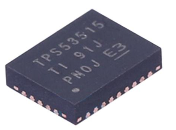


TPS53513RVER Replacement, Equivalent, Applications & Alternatives Guide
Contents
A practical engineering and procurement guide to the Texas Instruments TPS53513RVER 8A synchronous buck converter.
What Is TPS53513RVER?
The TPS53513RVER is a high-performance synchronous step-down DC/DC buck converter from Texas Instruments. It is designed for point-of-load power applications where a higher DC input voltage must be converted into a lower and tightly controlled output voltage.
The device supports a conversion input voltage range of 1.5V to 18V and an output voltage range of 0.6V to 5.5V. It can deliver up to 8A of continuous output current. The device integrates high-side and low-side MOSFETs, reducing the number of external power components required in the regulator design.
TI specifies integrated MOSFET resistance of approximately 13.8mΩ for the high-side MOSFET and 5.9mΩ for the low-side MOSFET. The device also includes D-CAP3 control, Auto-Skip Eco-mode, FCCM, precharged startup, output discharge, Power Good, and eight selectable switching frequencies from 250kHz to 1MHz.
In simple terms, TPS53513RVER is a compact power-management IC designed to provide a stable low-voltage power rail for processors, FPGAs, DSPs, communication devices, and other digital loads.
TI currently lists the TPS53513 as an ACTIVE product, which means it remains an officially supported product rather than a discontinued device. The current TI product page also identifies the RVE package as a 28-pin VQFN-CLIP package with a nominal 3.5mm × 4.5mm body size.
What Does TPS53513RVER Actually Do?
The main purpose of TPS53513RVER is to perform DC voltage conversion. A system may receive 12V, 5V, or another intermediate DC voltage, while a processor or digital IC may require a much lower voltage such as 1.0V, 1.2V, 1.8V, 2.5V, or 3.3V.
Instead of using a linear regulator to remove the extra voltage as heat, a synchronous buck converter uses high-frequency switching and energy-storage components to convert the input voltage more efficiently.
This makes TPS53513RVER particularly useful when the load requires several amperes of current. At an 8A output level, power efficiency and thermal performance become much more important than they would be in a small low-current regulator.
The device is especially suitable for point-of-load architectures. In a POL design, power is converted close to the load instead of sending a low-voltage, high-current rail over a long PCB or cable path.
This approach can reduce voltage drop, improve transient behavior, and make it easier to supply modern processors and high-speed digital ICs.
TPS53513RVER Applications
TPS53513RVER is not designed for only one type of electronic product. Its combination of 8A output capability, adjustable output voltage, integrated MOSFETs, fast transient response, and compact package makes it useful across several power-intensive digital systems.
Server and Cloud Computing
TPS53513RVER can be used in point-of-load power architectures for servers and cloud-computing hardware. Local regulators can provide power to processors, memory-related circuits, networking devices, storage controllers, and other digital subsystems.
Networking Equipment
Network switches, routers, communication platforms, and optical networking equipment often require several regulated voltage rails. TPS53513RVER can convert an intermediate bus voltage into a lower-voltage rail for digital and communication ICs.
FPGA Systems
FPGAs can create fast changes in current demand when logic activity changes. TPS53513RVER supports FCCM and D-CAP3 control, making it suitable for applications where transient response and output-voltage behavior are important.
DSP and Processor Boards
Digital signal processors and embedded processors often require stable low-voltage rails with several amperes of current. The adjustable 0.6V to 5.5V output range gives engineers flexibility when designing processor power rails.
Industrial Electronics
Industrial controllers, automation systems, embedded computing platforms, and instrumentation equipment can use the device as a local DC/DC power stage for processors, FPGAs, communication interfaces, and other digital loads.
Telecommunications Equipment
Telecommunication infrastructure often contains multiple digital subsystems operating at different voltage levels. A compact synchronous buck converter can help generate local rails while maintaining good efficiency and power density.
TI's official documentation specifically lists server and cloud-computing POLs, broadband and networking infrastructure, optical communications infrastructure, and I/O supplies among the applications for the TPS53513 family.
Key Advantages of TPS53513RVER
8A Continuous Output
The 8A continuous output capability gives the device enough current capacity for many processor, FPGA, DSP, networking, and industrial point-of-load applications.
Integrated MOSFETs
High-side and low-side MOSFETs are integrated into the IC. This reduces external power-stage components and can help simplify PCB design.
Fast Load-Step Response
D-CAP3 control and adaptive on-time operation help the converter respond quickly to changes in load demand, which is valuable for modern digital processors and FPGAs.
Wide Output Range
The 0.6V to 5.5V adjustable output range covers many commonly used digital supply rails.
Flexible Switching Frequency
Eight selectable switching frequencies from 250kHz to 1MHz allow engineers to balance efficiency, transient performance, component size, and EMI requirements.
Compact Package
The 28-pin VQFN-CLIP package has a nominal 3.5mm × 4.5mm body size, making it attractive for space-constrained power designs.
Another important advantage is the relatively low external component count. TI describes the TPS53513 as a space-conscious solution that does not require an external compensation network. This can simplify the power design and reduce PCB complexity when the recommended design guidelines are followed.
TPS53513RVER Replacement and Equivalent Options
One of the most common questions from engineers and purchasing teams is: What is the best TPS53513RVER replacement?
The correct answer depends on what "replacement" means.
A functional alternative may perform a similar power-conversion function but require PCB or component changes. A parametric equivalent may have similar input voltage, output current, switching frequency, and output voltage specifications but still have a different pinout or control architecture. A pin-to-pin replacement is a much stricter requirement.
These three categories should never be treated as identical.
| Part / Family | Current Class | Relationship | Replacement Consideration |
|---|---|---|---|
| TPS53513RVER | 8A | Original device | Reference design and baseline |
| TPS53515RVER | 12A | Same family / higher current | Requires pinout and design verification |
| TPS548A23 | 12A | Newer related alternative | Different pinout; not an automatic drop-in |
| TPS548A28 | 15A | Higher-current alternative | Design qualification required |
Texas Instruments currently identifies the TPS53515 as a higher-current related device within the TPS53513 family, while also listing newer products such as TPS548A23 and TPS548A28 as related alternatives. However, TI explicitly distinguishes products with different pinouts from true pin-for-pin alternatives.
For this reason, TPS53515 should not simply be soldered into a TPS53513RVER PCB without checking the schematic, pin assignment, external components, thermal behavior, current-limit configuration, and PCB layout.
TPS53513RVER Alternative Comparison
TPS53515 as a Higher-Current Alternative
TPS53515 is one of the most logical parts to investigate when an application requires more current than TPS53513RVER can provide.
TPS53515 supports up to 12A continuous output current while retaining many important characteristics of the TPS53513 family, including a 1.5V to 18V input range, 0.6V to 5.5V output range, 600mV ±0.5% reference, D-CAP3 control, Auto-Skip Eco-mode, FCCM, and selectable 250kHz to 1MHz switching frequencies.
However, higher current capability does not automatically make TPS53515 a better replacement. If an existing product was designed around an 8A maximum load, the additional current capability may provide little practical benefit.
TPS548A23 as a Newer Alternative
TPS548A23 is another interesting alternative for engineers starting a new design. TI describes it as a 4V to 16V, 12A synchronous step-down converter with higher efficiency in a smaller package.
The important point is that it should be considered a new-design alternative rather than automatically classified as a drop-in replacement. A different input range, package, pinout, control behavior, and external component requirement can affect the entire power stage.
TPS548A28 for Higher Current Requirements
TPS548A28 is positioned at a higher current level, with up to 15A output capability and features such as remote sensing and an integrated 3V LDO. It can therefore be attractive for a new design that has moved beyond the 8A range.
However, engineers should evaluate it according to the complete system requirements instead of choosing the largest current rating simply because it is available.
Should You Use a TPS53513RVER Replacement?
The answer depends on the product stage.
For an Existing Mass-Production Product
If TPS53513RVER has already been qualified and is working reliably in a mature product, replacing it only to save a small amount of component cost is usually not recommended.
A power IC replacement can trigger PCB changes, thermal validation, EMI testing, load-transient testing, startup testing, protection testing, reliability testing, and production requalification.
The engineering cost can easily exceed the unit-price savings.
For a New Product
If the design is still at the schematic or prototype stage, engineers have much more freedom. In this situation, TPS53515, TPS548A23, TPS548A28, or another current-generation regulator may be worth evaluating.
The correct choice should be based on output current, input voltage, efficiency, thermal performance, switching frequency, PCB area, EMI, availability, and long-term supply strategy.
For Supply-Chain Risk Management
A second source or alternative should be qualified before the original component becomes difficult to obtain.
This is particularly important for products with long production cycles. The goal should not be to find the cheapest substitute after a shortage occurs. The better strategy is to identify, test, and approve an alternative while the original component is still available.
For high-reliability products, treat a TPS53513RVER alternative as an engineering qualification project rather than a simple purchasing substitution. Verify electrical, thermal, mechanical, control-loop, EMI, and production-level performance before approval.
Can a Replacement Deliver the Same Performance?
A replacement can potentially achieve similar or even better system performance, but similar headline specifications do not guarantee identical behavior.
For example, two buck converters may both support 8A output current, but they can behave differently during a fast load step. Their control loops, current limits, switching frequencies, MOSFET losses, thermal resistance, minimum on-time, startup behavior, and protection mechanisms may all be different.
Before approving a TPS53513RVER equivalent, engineers should compare:
- Input voltage range
- Output voltage range
- Continuous output current
- Peak current and current-limit behavior
- High-side MOSFET resistance
- Low-side MOSFET resistance
- Switching-frequency range
- Control topology
- Feedback and reference accuracy
- Minimum on-time
- Startup behavior
- Protection functions
- Thermal performance
- Package and pinout
- External component requirements
- PCB layout requirements
A replacement should therefore be evaluated at the system level, not simply by comparing the maximum output current shown on the datasheet.
Why Is TPS53513RVER in Demand?
The demand for TPS53513RVER is closely related to the continuing need for efficient point-of-load power conversion in high-performance digital systems.
Modern processors, FPGAs, networking ICs, storage controllers, and communication devices increasingly require lower supply voltages while drawing substantial current. This creates a strong need for compact regulators that can deliver several amperes without excessive power loss.
The TPS53513 family addresses this requirement with an 8A output capability, integrated MOSFETs, adjustable output voltage, selectable switching frequencies, and control features designed for fast load changes.
Another factor is design familiarity. Once a power-management IC has been used successfully in a platform, engineers and manufacturers may prefer to continue using the same device family because the reference design, PCB layout, validation data, and production process are already established.
This does not mean that demand for a specific part number will remain unchanged indefinitely. Component demand can be affected by product cycles, semiconductor supply conditions, new-generation regulators, system architecture changes, and manufacturer product roadmaps.
Future Trends in High-Current Power ICs
The broader power-management market continues to move toward higher current density, smaller packages, improved efficiency, better transient response, and more integrated power stages.
For digital systems, future power IC designs are likely to place even more emphasis on fast load-transient response and thermal efficiency. As processor and accelerator power demands increase, the distance between the regulator and the load becomes increasingly important.
Newer regulator families may also integrate more functions, including remote sensing, additional monitoring, improved protection, and higher-current capability. These features can reduce system-level component count and improve power density.
For engineers maintaining an existing product, however, newer does not automatically mean better. A mature TPS53513RVER design may remain a practical solution when it has already passed electrical, thermal, EMI, reliability, and production validation.
For a new design, engineers have more flexibility to compare newer products based on efficiency, package size, current capability, control architecture, availability, and long-term support.
Final Recommendation
The TPS53513RVER is an 8A synchronous buck converter designed for high-current point-of-load power applications. Its combination of integrated MOSFETs, adjustable output voltage, flexible switching frequency, fast transient response, and compact package makes it suitable for processors, FPGAs, networking equipment, servers, industrial electronics, and telecommunications systems.
When looking for a TPS53513RVER replacement or TPS53513RVER equivalent, engineers should distinguish between a functional alternative, a parametric equivalent, and a true pin-to-pin replacement.
TPS53515 can be investigated when higher current capability is required, while TPS548A23 and TPS548A28 may be relevant for newer designs with different system requirements. These parts should not be treated as automatic drop-in replacements without complete design verification.
For an existing qualified product, keeping the original TPS53513RVER may reduce engineering and requalification risk. For a new design, newer alternatives may provide additional flexibility and performance.
The most reliable replacement strategy is to compare the complete electrical and mechanical specifications, verify the PCB and pinout, evaluate thermal and transient performance, and complete appropriate qualification testing before production approval.